BMG Notes as of October 2002
Written by Sean Markan - markan@mit.edu
Overview
The BMG (Building Model Generation) Project aims to construct a realistic model of the MIT campus in a fully automated manner. In our conception of the final project, up-to-date architectural data (floorplans) is provided by the Department of Facilities (potentially along with data from other sources), and is processed to create a 3d model of campus browseable online. BMG also interprets the floorplans to associate regions in space with named rooms, and to identify adjacent spaces. To make these two forms of data available to a broad range of applications, they are fed into an API currently under development by Jason Bell. All this processing takes place as a regular cron job so as to maintain accurate models of campus even as the DOF updates their plans.
The pipeline just described for BMG has already been implemented in a rough form, although most parts of it need substantial work to produce appealing models. This summer I worked with Will Leiserson and Jason Bell on the BMG project, and so what follows is a description of my work, as well as (hopefully) sufficient information for newcomers to get started on the project. I should emphasize that most of the work described in this document was done by my predecessors, but is included because I think additional explanation will be useful for future participants in the project.
Pipeline Details
At present, the overall BMG script begins by analyzing the campus basemap (2dbase.ug, which is actually an outdated version) to generate a list of buildings. A list of building numbers and their associated contours on the basemap is formed in the files bldg_nums and bldg_contours. However, this procedure is buggy and should be replaced with one using data directly from the Department of Facilities (as described later on). For this reason, if you are just joining the project, you probably don't need to worry about any of the code that does this analysis.
Once a list of buildings is generated, the script iterates through it and performs the following steps for each building:
- Floorplan files are downloaded from the DOF-maintained website floorplans.mit.edu. At this point they are in AutoCAD version 12 format. As versions are available in more recent formats, we should probably switch to those at some point. For more details on floorplans, see below.
Above: A representative region of a floorplan
- Each floorplan is converted from AutoCAD into UG by the program
acad2ug (not sure of the source of this program).
- Each floorplan is cleaned up by a program called
dejunk (written by Will). In addition to fixing erroneous geometry and converting closed wires to faces (see UG section), this program finds doors, windows, and other symbols on the floorplans and moves them onto their own layers.
After dejunk
- The program
walls (written by me this summer), extrudes each processed floorplan into a 3d Unigrafix model of the corresponding floor. It handles doors, windows, structural elements, and roofs, but is buggy. It also generates a Unigrafix file that "wraps" the floor files using inline statements, using appropriate transformations. Thus, this file points to the geometry for the entire building. Finally, walls produces files describing the adjacencies between rooms and portals on each floor. We intend to include this data in the UG files themselves eventually.
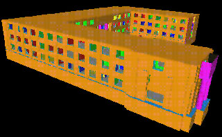
A complete building
- Each file produced by walls (one per floor, plus the container file) is converted to Open Inventor (.iv) format by
ug2iv (written by Will). The floors can then be viewed separately or together with the utility ivview. The utilities ivToVRML and vrml1tovrlm2 permit conversion to VRML, although our script does not call them.
Once this process has been performed for each building, the program placement creates another container file (campus.ug) that includes each building. Buildings are translated and rotated by matching their bounding boxes to contours on the basemap, but this process is somewhat unreliable. It should also be superceded by using transformation data directly from DOF.
The final step of the process is to convert campus.ug to campus.iv, using ug2iv. Here are larger illustrations of this process.
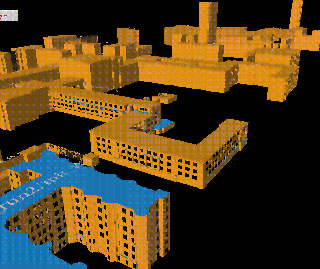
The campus model
Building BMG / Source tree
All code connected with the current version of BMG resides in the CVS repository walkthru/mit. walkthru/BMG contains code from earlier work, and walkthru/SLAM contains other potentally useful material. To build the BMG programs for yourself:
- Set the environment variable
CVSROOT to /d9/projects.
- In the target directory, type
cvs checkout -P walkthru/mit. The -P is a useful CVS option meaning "prune," or "don't check out empty directories." This is necessary because there is no (easy) way to remove a directory from the repository, so the BMG group simply emptied directories we no longer needed. At this point, the directory tree is as follows:
aux/ This contains configuration files for the model-building process, as well as sources of data that we do not download from the web (i.e. campus basemap).
documentation/ Self-explanatory.
src/ Source code for all the programs we've written.
- In the
walkthru/mit directory, run ./super_make.csh mybuild, where mybuild is the name of the target directory where you want new files placed. The target directory must not exist yet. All construction of models will take place within mybuild/, whereas development of BMG should probably take place within the other subdirectories of mit/.
- cd into
mybuild/. Here, the subdirectories are:
aux/ Same as above - when super_make.csh is run, files are simply copied from mit/aux/ to here.
bin/ Binary files - super_make.csh triggers builds of all the binaries within mit/src/, and the binaries are copied here.
build_campus This is Will Leiserson's script interpreter, which we use to call the programs needed to build a model of campus from scratch. It is not specific to the BMG project (as the name might suggest), but rather executes the script specified in run_script.txt with the options specified in run_config.dat. We have simply written these files to control the model-building process. Also, note that the script interpreter automatically generates files errors.dat and report.dat as output whenever a script is run.
intermediate/ This directory stores some of the intermediate files for the campus build process. There may also be intermediate files produced at this directory level, but it might be a good idea to eliminate this behavior in the future.
models/ Floorplans, intermediate UG models, and the final models of campus are all placed here when build_campus runs.
- Run
./build_campus. If all goes well, the campus build will proceed to download floorplans from the web, interpret and extrude them, and assemble a model of campus. If not, ./build_campus will either fail or crash; in either case, you should begin with the logfiles (report.dat and errors.dat) to diagnose the problem.
Structure of floorplan data
This section describes what I have learned about the MIT floorplans; hopefully it will be of use to future participants in the project.
Filename and Layer Conventions
MIT floorplans, as published on floorplans.mit.edu, are named in the form 3.4.dxf, where 3 is the building number and 4 the floor number. Floors 0 and 00 (if they exist) are below ground, and floors numbers ending in M are mezzanines. If a floor number ending in R exists, it is a drawing of the roof and contains no habitable spaces. Otherwise, the roof can be assumed to cover the highest-numbered floor. Within each CAD drawing, the following layers are present:
- A-SHBD
Page border in original plans - contains useful information such as scale, building name, and compass rose.
- A-WALL-CORE (red)
This layer contains structural elements such as exterior walls and supporting columns. Staircases also seem to be in this layer.
- A-WALL (blue)
This layer contains almost all other architectural elements, including interior walls, doors (denoted by arcs) and windows (denoted by 3 parallel lines).
- A-AREA-IDEN (black)
This layer contains text strings labeling spaces, as well as lines to indicate callouts. However, according to DOF, this format will soon be replaced by blocks positioned inside rooms - one block per inhabitable space. The block will then contain the room label.
- A-MISC (green)
Used for miscellaneous markings, including which direction stairs run and where buildings connect to other buildings.
- A-AREA-FICM (cyan)
This layer is used for space accounting and contains a closed contour for each inhabitable space (room, hallway, etc.)
- A-AREA-FICM-SHFT (orange)
This layer is similar to A-AREA-FICM, but contains contours for shafts instead of rooms.
- A-AREA-FICM-GROS (magenta)
This layer contains the exterior contour for each floorplan.
Above: A section of the 1.0.dxf floorplan, viewed with two different sets of layers turned on.
Symbolic Conventions
Most of the symbols on the floorplans are self-explanatory, but here are a few additional pieces of information:
- X's represent elevators
- Walls are always represented by double lines. When isolated single lines occur, they can mean any number of things, including movable partitions (like cubicles), counters, or shelves. (Note that here, "single lines" does not mean closed contours on the A-WALL-CORE layer - these are typically structural elements.)
- Atriums (e.g. Lobdell cafeteria) are marked by the text "OPEN BELOW" on floors above the bottom of the atrium.
UG Files
Due to the ease of parsing Unigrafix (UG) files, the BMG group has been using it as our intermediate file format of choice. Earlier this summer, Will Leiserson and I found that the standard Unigrafix library was too difficult to use, so I have written the library that our programs are currently using to parse and edit UG files. The current version can be found in the src/CADlib directory, although I have been working on a new version that will use STL and be more robust.
The UG specification can be found via a link from the BMG homepage, but I will briefly describe it so as to avoid confusion.
Unigrafix primitives are wires, faces, and vertices. A wire is a sequence of vertices connected by line segments, and a face is the polygon defined by a sequence of coplanar vertices. Every face and wire can also have a color, which is specified by a color name after its geometry data. Colors in turn have their own definitions. By way of example, consider the following UG code:
c_rgb RED 1 0 0 ;

v A 0 0 0 ;

v B 0 0 1 ;

v C 0 1 1 ;

v D 1 0 1 ;

w mywire ( A B C D ) RED ;

f ( A B D ) ;
The geometry this represents is shown at right. The c_rgb tag defines the color RED, and the v, w, and f tags define vertices, wires, and faces, respectively. Note that both names (like mywire) and colors are optional for primitives.
In addition to encoding geometry, UG files provide a way of defining geometry and reusing it. Enclosing UG tags by a pair of def and end tags defines a group of objects that can then be instantiated by the i tag. For example, the code
c_rgb RED 1 0 0 ;

def mygeometry ;

v A 0 0 0 ;

v B 0 0 1 ;

v C 0 1 1 ;

v D 1 0 1 ;

w mywire ( A B C D ) RED ;

f ( A B D ) ;

end;

i (mygeometry);
would produce identical results to the last sample. Note that nothing would have been drawn had we not included the i tag. An i tag can include a transformation to apply to its geometry as well. Finally, note that a UG file can include another by means of the inline tag. See the specification for more details.
CADlib library
Several programs in BMG use the classes in CADlib to represent 3d geometry. This library essentially parallels the organization of data in a UG file, with a few modifications. CADlib includes the following classes:
ug_CADSpace
A "space" in which geometry exists. This parent object is used for keeping track of the other objects, and it is the object that translates to a UG file.
ug_def
This class was originally called ug_region due to our partial understanding of the UG file format - "region" and "def" are thus synonymous in the code. ug_def is used to represent a definition (def/end pair) in a UG file, so that every geometrical object in the file is contained in exactly one ug_def (objects outside any def in the actual file are considered to be in the top level ug_def - ug_CADSpace::nullRegion).
ug_vert
A named vertex, just as in a UG file. Each ug_vert object contains a list of wires that contain it.
ug_wire
A wire or a face. Each ug_wire object contains a list of vertices it contains. Wires can be closed or open.
ug_edge
A single edge of a wire or face. This is not part of the UG specification, but I found it useful in manipulating geometry. Note that each edge belongs to at most one ug_wire - wires can share vertices but not edges. A ug_edge can also exist without a "parent."
ug_instance
An instance of a definition, corresponding to the UG i tag.
ug_inline
A reference to another UG file, corresponding to the UG inline tag. A ug_inline object merely contains the name of the file it points to, and when a UG file is parsed, inlined files are not traversed.
ug_layer
The equivalent of a color in UG.
ug_sel
A collection of wires; contains a list of vertices and edges that its wires use.
CADstuff implements routines to check various properties of geometry (coincidence, whether edges are parallel, and so forth), and to modify it by extruding and moving objects. For more details, see the source code in /src/CADstuff. I should point out that the object destruction in CADlib is probably severely broken. I hope to remedy this (and to convert CADlib to use STL) at a future date.
Building Extrusion
Function of walls
walls, the program I wrote to extrude floorplans, operates on the building level (i.e. it process an entire building at one time). It takes as command line arguments the target directory for the model, as well as the floorplan files to use (in order). Its output consists of several sets of files:
For each floorplan x,
x.3D.exterior.ug
An extruded model of the outside of the floor
x.3D.ug
An extruded model of the entire floor
x.adjacency.portals and x.adjacency.rooms
Data on portal-room adjacency
For the entire building,
bounds.dat
This file contains points on the outer contour of the building, later used by the program placement to establish a bounding box for the building.
building.high.ug, building.med.ug, and building.low.ug
These three files are models of the building at high, medium, and low levels of detail. The high-LOD model is actually a container file that simply includes x.3D.ug for each floor, as well as a few other pieces of geometry such as roofs. (Ultimately, such extra geometry should have its own file.) Similarly, the medium-LOD model is a container file that uses x.3D.exterior.ug for each floor instead. building.low.ug is just a capped extrusion of the exterior contour of the building's ground floor.
building.iv
For viewing purposes, all three of the models just described are converted to Open Inventor format by ug2iv. The role of building.iv, then, is to add dynamic level-of-detail behavior. This file includes an LOD node that switches between rendering the three versions based on the distance of the camera from the center of the building.
Once the build script has run for a particular building, the final model for that building is building.iv (in the appropriate directory).
Details of walls
 This section outlines the steps
 walls uses to extrude buildings. For implementation details, see the source code in /src/walls/. walls makes two passes through each floorplan it is given, extruding each individually in the first and combining them in the second. Floorplans are processed as follows in the first pass:
First, the file is parsed into a ug_CADSpace object (see the previous section on CADlib). The floorplan is then analyzed to build what is essentially a graph, with rooms as nodes and portals as edges. Each contour on the A_FICM_AREA layer of the floorplan is taken as a room, and those rooms are named according to their labels (if a label can be found within the room contour). Shafts, windows, and doors, and adjacency information are organized into a floorModel object. Within each room, "panels" are identified to represent walls. A panel here is just a plane perpendicular to the floor, so a panel will be created above each door and above/below each window. The entire room contour, minus identified portals, is assumed to represent walls.
Next, structural elements (supporting columns, etc.) and the exterior contour of the floor are added to the model of the floor. Room-portal-room adjacency data for the floor model is written out to separate files. (This will soon change though, as Jason and I plan to incorporate adjacency data into the output UG file in the form of comments.)
The floor model is then extruded into a new CADSpace, constructing the planes prescribed by the panels, frames for doors and windows, and floors/ceilings. Note that ceilings are currently commented out for visualization purposes. If the floorplan is the last in the command string, a roof is put on top. The colors currently selected are essentially irrelevant, but the scheme is as follows: orange for exterior walls, gray for floors, purple for structural elements, and a randomly chosen color (of red, blue, green, and yellow) for the walls of each room.
If the floorplan is determined to be the first one above ground, its approximate center and size is found for use with the level-of-detail node in the final IV file, and its boundary points are saved for later use with placement.
Finally, the high- and medium-LOD versions of the extruded floor are written to separate files (the medium version contains only the exterior of the floor, and there is no low-LOD version of individual floors).
The second pass through the floorplans is used to assemble them into a building (by means of container UG and IV files). Before it begins, high- and medium-LOD CADSpaces are constructed to hold the inline objects that will point to individual floors. Then, each floorplan is aligned to the ground floor (by moving one of its corners directly above a corner of the ground floor), and a reference to the corresponding UG files is added to the container CADSpaces. Areas where one floor's footprint does not cover the one below it are patched.
Once this pass is complete, the high- and medium- LOD container files are written to disk. Also, a low-LOD model is built by extruding the exterior contour of the bottom floor, and it too is saved to disk. Finally, walls writes a wrapper IV file (building.iv) for the entire building, including the appropriate LOD node and file references. Note that walls does not create any of the other IV files referenced by building.iv; this is done by ug2iv later on.
Topography / Basemap Attribution
In addition to models of buildings, a major component of BMG models will be their external surroundings - ground coverings, outdoor objects, etc. So far, some progress has been made in assembling this geometry, although it has not been integrated into the automated pipeline.
When I joined the project, it already included two datafiles describing local topography (a point set and a contour map), as well as programs to build a triangle mesh out of this data. This code can be found in the CVS repository in the directory /walkthru/BMG/Basemap.ok. The subdirectory Terrain contains the raw AutoCAD data and a Perl script for parsing it into a list of points. If you choose to experiment with this code, you may wish to change the Perl script to include only a subset of the entire raw data points so that triangulation and rendering will run reasonably fast. The Perl script makes it clear how to do this. To actually create the ground mesh, change to the directory /walkthru/BMG/Basemap.ok/Building and run ./MIT. (Note: if you changed the Perl script as suggested, you will have to run it again and copy its output into the /Building directory.) Among other things, MIT performs the triangulation on the point set and creates a model of the ground. (One more note: the last time I tried this program it seg faulted, but only after outputting the terrain model. I am not sure what happened.)
Since I began working on the terrain aspect of BMG towards the end of my time on the project, the additions I made are not as functional or complete a they could be. However, I have moved the code I was working on last into the repository directory /walkthru/mit/src/terrain so that it can be examined by anyone who wants to create a better version.
Most of my work was directed towards basemap attribution - taking the basemap provided by DOF and determining which regions should be treated as pavement, grass, sidewalk, and so forth. The map will be turned into a mesh of appropriately colored triangles. Once we have a reliable means of doing this, the intent is to "superpose" the triangulation of the basemap with the triangulation of the topography so that each edge is preserved (though it may be split, and there may be new edges). Each vertex will then receive its height information from the topography triangulation, and each face will receive its coloring from the colored basemap triangulation. The coloring is a non-trivial problem because the basemap file is a set of paths denoting boundaries between regions - not a set of closed contours. A contour on the L-SITE-WALK layer, for instance, always indicates a walkway on one side, but provides no indication of which side is the walkway. Furthermore, a walkway need not be surrounded by contours on that layer. I have not been able to find a robust heuristic to paint the map the way that "looks" correct, but have made some progress towards that end. The algorithm I used followed roughly the following steps:
- Begin by creating a triangulation that includes all the edges of the basemap.
- Identify contiguous patches (sets of triangles) that will be colored as one unit because they are not separated by any lines on the basemap. This is essentially a flood fill algorithm, but appropriate steps have to be taken to prevent the flood fill from bleeding through small cracks in the basemap lines. I required that the algorithm not pass edges below a certain length.
- For each patch, measure how much of its border belongs to each layer in the basemap. If this is a clear indication of what color the patch should be, color it (see code for details).
- When no more patches can be colored independently, attempt to propagate the coloring by employing rules about certain layers on the basemap. For instance, contours on the L-SITE-WALK layer typically border a region of grass and a region of sidewalk. If one side is colored, the other can be assumed to be the other color with reasonable consistency.
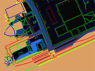
The flood-filling algorithm in progress
At the moment, this algorithm is implemented in the form of an OpenGL visualization, as I wanted to be able to watch it in progress and see where it went wrong. To run the program, build it with make and type ./painttest. Use the number keys 1 to 6 to step through the flood-filling algorithm in various increments (6 being 100,000, more than enough) until filling is complete. The program's output will say "Couldn't step" if you attempt to step further. You can then use the keys 'b' and 'c' to step through the attribution algorithm (1 and 100 steps at a time, respectively). 'a' toggles visualization of the floodfill algorithm, and 's' toggles visualization of the attributed colors. Note that this program was not meant to be part of the final pipeline, so it is not robust at all. If you wish to use it in ways besides the one just described, read the code so that you understand what is going on. Hopefully, someone will be able to improve the algorithms it uses and then rewrite them into a program without the extra confusion of visualization.
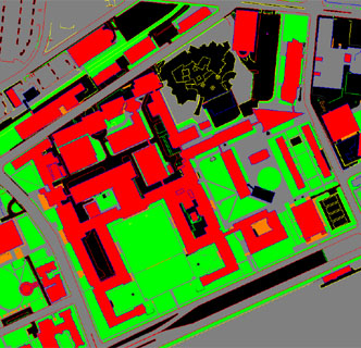
Preliminary attempt at attributing basemap
Regarding the basemap file used to generate forgc.ug, it was a modified version of Campus_Basemap.dxf. To solve problems with acad2ug and AutoCad, I had to use the rather ugly workaround of loading that file into another CAD package, removing unnecessary layers, and then passing it to acad2ug. I also had to delete a wire that was causing errors for unknown reasons.
Conclusion, Future Work, and Comments on DOF Meeting
I think that the work done by Will, Jason, and I in the past few months has resulted in numerous improvements to BMG. However, new enhancements to be made and problems to solve have been proposed constantly. Some of these are listed below.
DOF Meeting
In August, 2002, Prof. Teller, Jason Bell, and I met with two members of the Department of Facilities to discuss how we might better collaborate on producing campus models. A couple key points to come out of this meeting are as follows:
- Building placement. DOF indicated to us that they have a spreadsheet containing the names of all buildings on campus, as well as translation/rotation data for mapping their floorplans onto the coordinates of the basemap. Provided that we can obtain this data, it should easily eliminate several unreliable stages of processing from the pipeline, and is probably the next logical step for the BMG project. Instead of parsing the basemap for building names, we could take them from the spreadsheet, and instead of trying to do our own contour-matching for each building, we could use the transformation matrices DOF has effectively computed.
- Floorplan alignment. In the course of generating buildings, we found frequent inaccuracies in floorplan alignment. Typically, adjacent floorplans will be drawn slightly differently, so that there is no way to align them correctly (i.e. aligning them on one side makes them unaligned on the other). This results in cracks in the extruded 3D models. DOF has explained that these inconsistencies are a result of the complicated history of the floorplans, and will not be fixed in the foreseeable future. However, BMG has also decided not to pursue some sort of algorithmic smoothing process, so this remains an unresolved problem.
Future Work
At present, a number of items remain on the project's "to do" list. Here are the major ones:
- Vertical connectors.
walls is currently able to identify and draw portals between rooms on the same floor, but not rooms on adjacent floors. Some work will have to be done to build staircases and elevators in vertically connecting spaces.
- "Special" Levels. Floorplans ending in M (mezzanines) are currently ignored, but should be added. Additionally, some floorplans have rooms marked as "OPEN BELOW." As the name implies, these are atriums and should be extruded correctly.
- Robustness. This applies to many dimensions of the project. On the level of geometry, CADlib should include routines to clean up geometry it is fed. This includes eliminating duplicate vertices and consecutive, parallel edges from room contours.
CADlib may also need to be examined for places it is prone to crash if it encounters bad geometry. Finally, geometry should be "condensed" before it is written, to prevent programs from using many vertices in the same location for different wires/faces. On a semantic level, walls is still getting many details wrong. Why some levels/exteriors/other details are not drawn should be investigated, and errors should be flagged in the command prompt output and geometrical output.
- Heights Currently, the
floorModel class created for each level in walls provides default values for the z-coordinates of points in the extruded model, including floor heights. More specific data could be integrated into this process using height data we currently have (I'm not sure where though).
- Textures/styling. A provision should be added in the output of
walls for more specific geometry than the generic doors, windows, and other elements it now produces. One improvement would be textures, which could be applied by building to all elements of a certain type. I would also suggest creating a sort of "style file" for each building, which would contain specific geometry to be instanced for exterior windows, doors, etc.
- Miscellaneous. There are a few other suggestions in this document and in the source code where they are relevant.
Quirks, troubleshooting, and bugs
If you are working on BMG, you may want to look over this list so that if you encounter one of these problems, you will not have to rediscover what is going wrong.
- If you find that
ug2iv doesn't work:
If ug2iv is giving you a parse error on an automatically-generated UG file, check to see that the file does not contain any invalid floating-point numbers. When printed to the file, these will appear in the form nan...., which can't be parsed. If the output Open Inventor file doesn't work, check to see that none of the definition tags has a name containing a '#'. Unfortunately, some layers in the original AutoCAD are thus named, but Open Inventor treats '#' as the comment delimiter.
- If a building is not in the campus model or is drawn wrong:
Missing buildings seem to be missing because their names were not found by the program that analyzes the basemap. As I've mentioned, this step should be cut out of the pipeline and so will not be a problem. As for buildings, drawn incorrectly, there are number of errors whose sources I have identified but not had time/been able to correct. For one, the alignment algorithm simply fails on many floors. In particular, the floorplans sometimes contain diagrams of building sections that are not actually part of the floor in question, but are drawn using the same layers. These diagrams appear as parts of buildings floating in space, and should be removed somehow. Also, floorplans for the mechanical rooms on rooftops frequently end up misaligned because their outlines are much different from the contour of the actual building. DOF has told us that these plans should follow the alignment of the floor below them. On these rooftop floorplans, the building contour is also frequently drawn around two disjoint polygons, connecting them with one edge from the first to the second and an identical, oppositely oriented edge from the second to the first. These conflicting edges are responsible for the artifacts seen on some of the rooftops.
To future participants in the project:
Perhaps the most difficult aspect of this project was trying to modify existing code without sufficient explanation of what it did. I hope that this document will partially remedy this, although I realize that it too leaves many details unclear. For this reason, I would suggest maintaining a single, up-to-date piece of documentation, whether it begins with this one or an entirely new one. This way, the learning curve will not be so steep and older documentation will not be rendered useless as the programs evolve. That being said, please forgive my inexperience in writing clean code, and feel free to contact me with questions about the codebase, although I cannot guarantee I will know (or remember) their answers.
Acknowledgements
This document describes work done by me in the last few months and many others in the past few years. Regarding my work, I would like to thank Prof. Teller for giving me the opportunity to participate in the project, and for teaching me the many concepts of programming and computational geometry that made it possible. I am also grateful to Will Leiserson and Jason Bell for much programming assistance.